Showing posts with label R69S Motor Rebuild. Show all posts

Sunday, January 08, 2017

Drilling RHS oil galley in early twins blocks

Early blocks did not have RHS piston skirt oiling galley. This often leads to overheated RHS pistons and piston/cylinder scoring, and sometimes engine seizure. Scottie's can machine your block to include the oil galley, exactly like the later engine blocks. Machine shop time is about 3/4 hour. Call us for details.


Friday, October 11, 2013

Media Blasting Aluminum Cases

When refurbishing a motor, or an entire bike, it is often desired to improve the cosmetic appearance of the cast aluminum cases. There are several cast aluminum parts on the bike that benefit from being media blasted and those include:

  1. Engine block, timing cover (intermediate case), electrics cover (front cover) and the semi-circular door on the top of the engine,
  2. Heads and valve covers,
  3. Transmission case and door,
  4. Wheel hubs.
Many owners blast the bottom of the rear shocks and then paint them or clear coat them. However I prefer to have them cadmium plated. When cadmium plating, I do not blast them; I just send them off and have the plater take care of it. 

Scottie's workshop always media blasts cylinder heads when they are disassembled for refurbishing  and machine work during a head service or repair. We also blast the valve covers so they come back to the customer matching the newly cleaned cylinder heads. 

Because valve covers do not have any crevices, they can be media blasted without special consideration, so long as they are cleaned thoroughly after blasting to remove any residual media. 

Wheel hubs can be blasted only during a wheel rebuilding service.  Prior to building, the bearings and old spokes are removed and the braking surface is protected with masking tape. Then the wheel can be rebuilt. Once the wheel is spoked and trued, then the braking surface can be trued on a lathe.

Blasting Media

For ease of clean up and less wear on the case surfaces, I recommend using beads.


Vapor Blasting

Vapor blasting (or vapor honing) is a blasting process in which the part is media blasted with glass beads and then blasted again with a fine slurry of very small glass beads and water/chemical cleaning agent solution.  The resulting finish is stunning and far superior than blasting alone.  In addition to the fine satin finish of aluminum parts, the aluminum retains a resistance to staining.  At Scottie's Workshop, we only media blast parts that are to be powder coated or painted.  We vapor blast everything else. 

Engine and Transmission Cases

Before jumping into blasting your cases, you may want to give some thought to the end appearance of your bike after plating. For example, if you are rebuilding your transmission, and decide to blast it clean, consider how it will look when bolted back up to your motor, which may have its original patina. 

When refurbishing and/or restoring a /2, we will normally media blast all the cast aluminum, or we will blast none of it, preferring instead to "deep clean" and preserve the original patina as best as possible. I discuss deep cleaning in another article. 

The following photo illustrates a freshly blasted transmission case next to a deep cleaned, natural patina engine block. 


When media blasting cases, the primary risk is media contamination into the case.  By its very nature, media is highly abrasive and durable stuff and will immediately destroy the surfaces of  even hardened, machined parts, such as bearing races and gear faces.  You will never be able to clean out all the media. The size of the media, and the number of places it can hide inside the cases, even after deep cleaning, soaking and rinsing of the cases, there will always be a risk of contamination.  There are still folks out there destroying their engines and transmissions because of residual media left inside the case. When it comes to media blasting open cases, the answer is clear.  Don't do it! 

So how do you media blast a case without risking contamination. The answer is to seal the cases before media blasting.  Here's how we do it at Scottie's Workshop.

For the case, we use 1/4" polycarbonate sheet to make up some doors for the engine case openings. The base gasket serves as a handy template for tracing and cutting. 


RTV and base gasket nuts (and some washers) are used to seal the poly to the case.


The transmission (studs removed) makes a handy template for tracing and cutting a door for the bell housing. RTV and nuts and washers are used to seal the poly to the case.
The semi-circular door on top is sealed with RTV and tightened down. Other holes are sealed with rubber bungs, or aluminum plugs made on the lathe, as shown in the photo below.


On the transmission bench, my friend Blaise Descollonges has come up with a novel method to seal the many circular-shaped openings of the transmission case. 

Bungs were cut on a lathe from aluminum.
The bungs have beveled edges so that they seal air tight. 

The transmission door is sealed with RTV and a gasket.


The end result is that these aluminum cases can be safely media blasted without risk of contamination. 

Even so, we thoroughly wash and rinse the cases several times with soap and water using a garden hose and high pressure washer after media blasting to ensure that any residual media is washed away. 

The end result is worth the effort: clean and refurbished -- and beautiful! - cases! 

When having your /2 serviced or restored at Scottie's Workshop, ask us about our media blasting services!


************************

Addendum, I was over at Joe's shop building a motor and I decided to use some of Joe's blasting plugs since I was there. They were so nice and clever, I decided to take a picture and update this article.


Wednesday, September 04, 2013

Lapping valve seats

I was hanging out with Joe Groeger this past Sunday. I joined him for breakfast at his usual spot and we had some coffee and oatmeal together. It's wonderful how many people will stop and say hello to Joe and his dog Lola while he is eating breakfast.


Afterwards, we returned to the shop and he said, "Let's work on one of your projects. What have you got?"  I went out to my car and pulled out a pair of R69S heads that are going on my own bike as part of my long-running R69S motor rebuild.

I brought the heads back into the shop and put them down on the table by the door.  It was then that Joe noticed that the lighting for this table isn't too good.  When you are 94, I suppose you need good lighting. So Joe set about trying to rig up some lighting for his table. When you are Joe Groeger, you can't just string an extension cord across the floor and setup a table lamp. You have to do it "right" ... hang some 2x4's from the ceiling joists, reinforce them with a triangulate, tap into the correct lighting circuit, run new electrical flex conduit from a junction box down the 2x4s, and then install a grounded 4-plug outlet box about 3' off the table.  This is why Joe's shop is so amazing.  Even when he is building something for himself, he builds everything  so that it will perform flawlessly for another 100 years.  And Joe is 94 years old.


So yes, Joe does have a way of getting side tracked on shop projects while he working on other projects. These side projects are often fantastic and wonderful in nature, so I don't usually complain when we get off-track. I just go with the flow and I usually learn something fantastic and wonderful from watching and helping. Last week Joe decided that the knob which tightens the collett on one of his lathes was too small and too hard to grip.


So we rooted around in his parts bin until we found a lovely wooden wheel that looked as if it had been made in 1925 and we transformed it into a lathe handle.  Talk about wonderful. I was in heaven.


But today I was a little under the gun. I've decided to get my motor swap done in time for the Norcal TT which is in 2 weeks.  I had to get these heads done today.  So with Joe preoccupied which his electrical project, I went in search of his box of tools for head reconditioning.  Joe keeps all of his tools in bins in a room dedicated to /2 engine work.  Each bin holds a selection of tools, jigs and parts for performing a particular job on a vintage BMW motorcycle. In this sancta sanctorum, the air is still and quiet and the aroma of bare metal and decade-old oils calms the mind.


On the top shelf I found an unlabeled box which contained some devices I recognized to be valve seat grinders. I also found some valve stem guide reamers and drifts, so I knew I had the correct box. I took the box out to the main workshop and emptied the contents on the bench.


I have always removed valve springs using one of those c-clamp looking things that reaches around the head and squeezes the valve from both sides. They are clumsy and awkward and always managed to slip off the face of the valve and send springs and keepers flying everywhere.  I did not find a valve spring compressor in the box so I asked Joe where I could find one and he walked over and showed me his system.


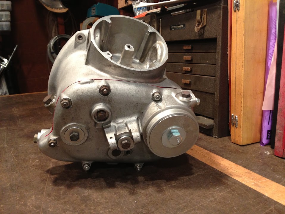
His valve spring compressor consists of a stand that he made which holds the head by the valve face.  Two "arms" hold the head and keep it from slipping off the stand.  Joe had made several windows bushings for various BMW models (R50, R60, etc.) and they were in the box.  You can see them in the photo above. The ends of the window bushings were stepped on a lathe so that they gripped the valve spring tops and would not slide off.  Once assembled, the entire unit was placed in the arbor press and the keepers were easily removed.  It was a simple (and fast) two-handed operation...and brilliant!


I was so excited that I forgot to take a photo of removing the keepers.  Here is a photo showing the head stand with the valve lapping tool installed.  (I'll get to that later.)


Next up was grinding the valves. Joe has a cool, old valve grinder that does a great job.


The valve guides on these heads are well within spec so I left them in place and just ran the reamer through with a hand tool to remove any carbon build up.  I then taped up the guides and media blasted the heads, valves, valve covers and finned exhaust rings.

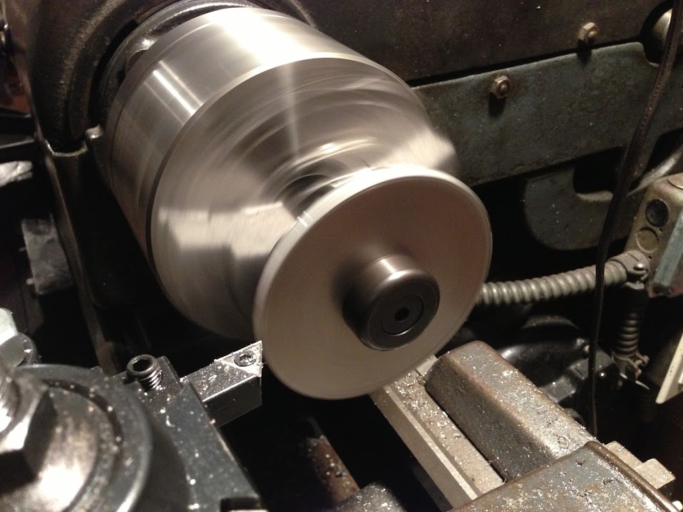
When it comes to lapping valves, I've always used one of those suction cups on a handle things that you spin between your hand. But I couldn't find it in the tool box.   "They don't work!" says Joe.  Joe's valve lapper is another one of those items in his shop that looks as if it was created as a side project during a main project, and built to last 100 years.


An old Jacobs chuck mounted to a shaft with a hand grip. After lubing the valve stem with oil and coating the valve seat with grinding compound, the chuck is tightened on the valve stem.  


Then, the entire assembly can be lifted up by the handle on the chuck and the head can be "swung" around in circles, effectively (and quickly) lapping the valve seats using the weight of the head. It is quick and easy and, again....genius. 

I had some video of me swinging the head around and lapping the valves, but my digital camera ate the footage. Next time I do it I'll try again to shoot video.

Putting the heads back together was a snap. 


My heads are now ready to go.

The only thing I am waiting on right now is a pair of Ed Korn's lightened wrist pins.  Once they arrive, I will be able to finish up the motor and break in the new motor before the big ride!


Monday, September 02, 2013

Lightening a /2 flywheel

The stock BMW flywheel is about 13 lbs of tool strength precision steel, drilled and balanced. It has the rear main seal surface on its flange.  Timing marks are stamped into its circumference. When lightening a flywheel, the goal is to reduce rotating inertia while retaining the timing marks and balance.

I start off by taking some measurements on the backside. This gives me a diameter where I can begin to cut into the depth of the flywheel. I want to be in control of how thick the finished flywheel will be.  To maintain strength and the rigidity to withstand the clutch spring without flexing, I want the flywheel to be no less than 1/4" at any given diameter.


 I am beginning to thin the flywheel.
Steel is removed from the face of the flywheel.  The flywheel remains in balance during the entire process and, unlike milling holes in the flywheel with a turn table on a mill, when lightening on the lathe, the flywheel does not need to be rebalanced after lightening. 
Using a caliper, the flywheel is shaped to follow the contour of the opposing side.
The left side of the flywheel is cut, leaving a thin ring about 1/4" wide which contains the timing marks. 

This ring can be undercut to minimize the amount of steel out near the "heavy" edge.  

The ring, about 1/4" wide and supported by enough metal to be strong and light, bears the original and unchanged factory timing marks. 
The final product weighs approx. 8.25 lbs, a weight savings of about 5 lbs.  Versus cutting holes in the flywheel on a mill, most of this weight loss on the lathe-cut flywheel is at its circumference, where weight matters most when the flywheel is spinning.

An 8 lb flywheel is not very aggressive. It is just enough of a weight savings to notice an improvement in engine response and faster shifting speeds but, because the flywheel is not excessively lightened, starting,  idle quality and drivability are not adversely affected. 

The most beneficial effect of lightening the flywheel is to allow the motor to spin down faster.  This is really helpful when upshifting. It's been my opinion that one of the things that slows /2's down is slow up shifts.  One must wait for the motor to "spin down" in order to let the clutch out into the next higher gear. For example, you're in 2nd and wound way out past the "II"  redline mark on the speedo. You begin to the pull the clutch in and apply upward pressure with your left toe. Click, there's third. The motor is still winding down. Taking its good old time. Meanwhile I'm ready to release the clutch. Even if I let the clutch out smoothly, the bike will lurch forward and jerk the whole driveline. So I'm left to wait until the motor spins down low enough where I can release the clutch and get back on the gas.  Anywhoosit.  Scottie's Workshop offers this service on /2 flywheels. The cost for the service is $150.  
Posted by Picasa

Tuesday, August 07, 2012

Project R69S /2 Motor rebuild: Removing the crank

Today, I'm going to remove the crank from this /2 bottom end.  This is part of the R69S motor rebuild project. The Slash Two motor is a wonderful little engine. Slash Two engines are virtually indestructable and run very well, even on very little maintenance.  

The main problem with this motor is the oiling system. In addition to a small gear oil pump, the crank bearings are oiled by centrifugal action.  Oil slingers on the main crank shaft whirl the oil inside a centrifuge and it is then pumped through the crank shaft hollow center. 

The centrifugal action causes the particles in the oil to separate and eventually harden inside the slinger. Once the slinger has filled up with particles, the oil hole is blocked and the crank bearings will no longer receive oil, leading to catastrophic results.

It is recommended that you tear down your Slash Two engine every 20k-40k  miles to inspect and clean the slingers.  

This is the process: 


Lock the flywheel and use a 41mm socket to remove the crank nut.
Note position of the locking washer.  If it is all bent up, put this on your parts list to order a new one.
Remove the flywheel.  This is a Bunch tool.
On the oil seal side, note position of the washer, and remove.
Inspect condition of woodruff key. This one has been around a while but is still servicable.
Remove the nuts and bolts on the bearing / oil pump cage.
Use a puller to remove the cage.  This is a Bunch tool #216. I have a peice of aluminum between the center screw and the crank nose to protect the crank nose.
Case removed.  I will leave the tool attached until I'm ready to reinstall.
Inspect bearings and oil pump gears.

Here's one-a-tha buggers we came here for. The front slinger.


The slinger screws should be punched with a screwdriver or cold chisel when installed. Always use new screws when reassembling.


Full slingers look like this.  This slinger came out of a motor that had destroyed its crank  rod bearings.  The cost of dirty slingers is a crank rebuild. If the journal bearings disintegrate it could throw a rod through the block or destroy other parts inside the motor.  


Use a hook to remove the oil seal and spacer.
Heat the case to 180'F
Position the Crank web like this and pull the crank out of the case. If it sticks use more heat!
Once the crank is free of the rear bearing, tilt it downwards like this.
Now you can wiggle the crank out , like this.
IT'S A GIRL!!  (I have a weird sense of humor.)
 
The crank is removed!  In the next episode, we'll remove the rear bearing and rear slinger.